MAGNABEND CENTRELESS HINGE
Following many requests I am now adding detailed drawings of the Magnabend centreless hinges to this website.
Please note however that these hinges are too difficult to make for a one-off machine..
The main parts of the hinge require accurate casting (for example by the investment process) or machining by NC methods.
Hobbyists should probably not try to make this hinge.
However manufacturers may find these drawings very helpful.
(An alternative style of hinge which is less difficult to make, is the PANTOGRAPH STYLE. See this section and this video).
The Magnabend CENTRELESS COMPOUND HINGE was invented by Mr Geoff Fenton and it was patented in many countries. (The patents have now expired).
The design of these hinges allows the Magnabend machine to be completely open-ended.
The bending beam pivots around a virtual axis, typically slightly above the working surface of the machine, and the beam can swing through a full 180 degrees of rotation.
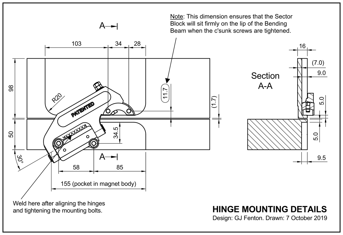
In the drawings and images below only a single hinge assembly is shown. However in order to define a hinge axis at least 2 hinge assemblies must be installed.
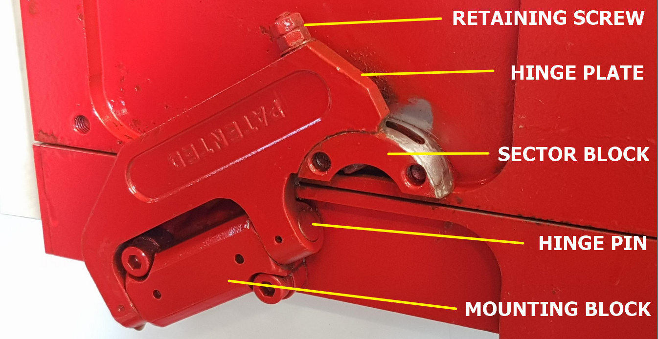
Hinge Assembly and Parts Identification (bending beam at 180 degrees):
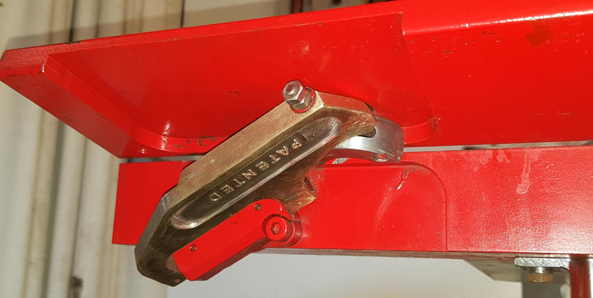
Hinge with Bending Beam in approx 90 degree position:
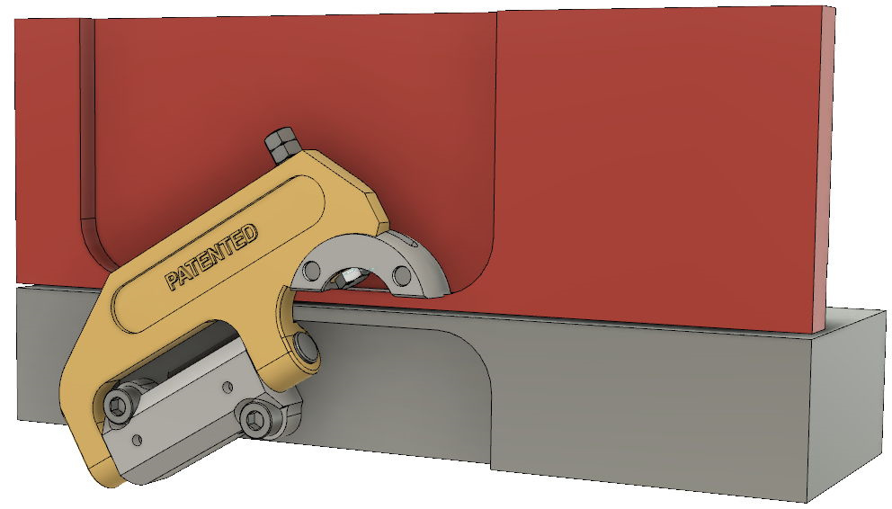
Mounted Hinge Assembly -3DModels:
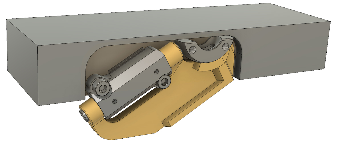
The diagram below is taken from a 3-D model of the hinge.
By clicking the following "STEP" file: Mounted Hinge Model.step you will be able to see the 3D model.
(The following Apps will open .step files: AutoCAD, Solidworks, Fusion360, IronCAD or in a "viewer" for those apps).
With the 3D model open you can look at the parts from any angle, zoom to see detail, or make some parts disappear in order to be able to see other parts more clearly. You can also make measurements on any of the parts.
Dimensions for mounting the Hinge Assembly:
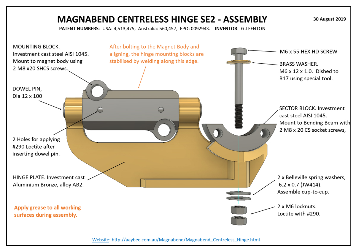
Hinge Assembly:
Click on the drawing for an enlarged view. Click here for a pdf file: Hinge Assembly.PDF
Detailed Drawings:
The 3D model files (STEP files) included below can be used for 3D printing or for Computer Aided Manufacturing (CAM).
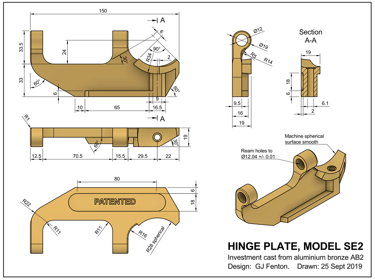
1. Hinge Plate:
Click on the drawing for an enlarged view. Click here for a pdf file: Hinge Plate.PDF. 3D Model: Hinge Plate.step
2. Mounting Block:
Click on the drawing to enlarge . Click here for a pdf file: Mounting_Block-welded.PDF, 3D Model: MountingBlock.step
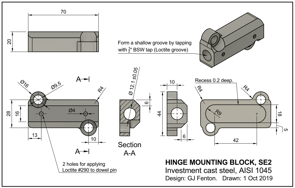
The Mounting Block material is AISI-1045. This high carbon steel is chosen for its high strength and resistance to swaging around the hinge pin hole.
Please note that this hinge mounting block is designed to be stabilised by welding to the magnet body following final alignment .
Also note the specification for a shallow thread within the hole for the hinge pin. This thread provides a channel for wick-in Loctite which is applied during hinge assembly. (The hinge pins have a strong tendency to work out unless they are well locked in).
3. Sector Block:
Click on the drawing for an enlarged view. Click here for a pdf file: Sector Block.PDF, 3D Cad file: SectorBlock.step
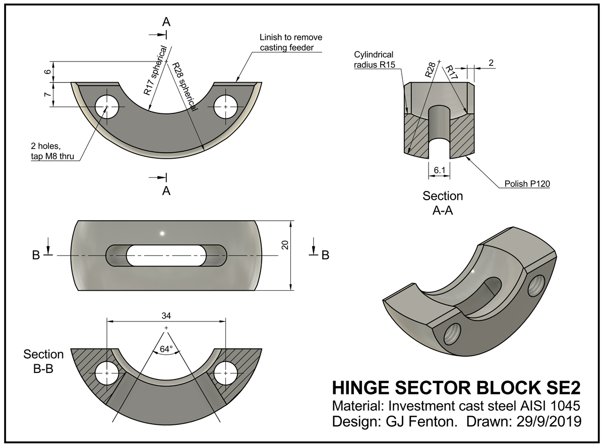
4. Hinge Pin:
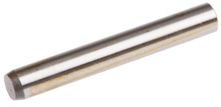
Hardened and ground precision steel dowel pin.
Diameter 12.0 mm
Length: 100mm
BOLTED-ON HINGES
In the drawings and models above the hinge assembly is bolted to the Bending Beam (via the screws in the Sector Block) but the attachment to the Magnet Body relies on bolting AND welding.
The hinge assembly would be more convenient to manufacture and install if welding was not required.
During the development of the hinge we found that we could not get enough friction with bolts alone to guarantee that the mounting block would not slip when high localised loads were applied.
Note:The shanks of the bolts themselves do not prevent sliping of the Mounting Block because the bolts are in oversize holes. Clearance in the holes is necessary to provide for adjustment and small inaccuracies in positions.
However we did supply fully bolted-on hinges for a range of specialised Magnabend machines that were designed for production lines.
For those machines the hinge loads were moderate and were well defined and thus bolted-on hinges worked well.
In the diagram below the Mounting Block (blue colour) has been designed to accept four M8 bolts (rather than two M8 bolts plus welding).
This was the design used for the production-line Magnabend machines.
(We made about 400 of those specialised machines of various lengths mainly during the 1990's).
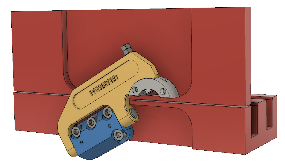
Please note that the upper two M8 bolts tap into the front pole of the magnet body which is only 7.5mm thick in the area under the hinge pocket.
Thus these screws must not exceed 16mm long (9mm in the mounting block and 7mm in the magnet body).
If the screws were any longer then they would impinge on the Magnabend coil and if they were any shorter then there would be inadequate thread length, meaning that the threads might strip when the screws were torqued to their recommended tension (39 Nm).
Mounting Block for M10 Bolts:
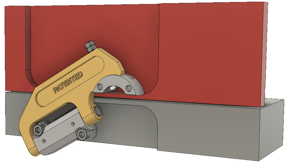
We did some testing where the mounting block holes were enlarged to accept M10 bolts. These larger bolts can be torqued to a higher tension (77 Nm) and this, combined with using Loctite #680 under the mounting block, resulted in more than sufficient friction to prevent slipping of the mounting block for a standard Magnabend machine (rated to bend up to 1.6mm steel).
However this design needs some refinement and more testing.
The diagram below shows the hinge mounted to the magnet body with 3 x M10 bolts:
If any manufacturer would like more details about a fully bolted-on hinge then please contact me.

